Getting started
Introduction
SD-WAN (Software‑Defined Wide Area Network) is a modern networking approach that helps enterprises manage connectivity by focusing on application performance and control.
It relies on a software-driven, centrally managed architecture that routes traffic across multiple network links and automatically selects the best path based on real-time conditions and business policies.
By contrast, traditional WAN (Wide Area Network) architectures rely on static, hardware-based designs. Most use MPLS (Multiprotocol Label Switching), a private network technology provided by telecom operators. MPLS uses fixed, predefined paths to carry traffic. While reliable, this approach is less flexible, more costly, and offers limited visibility into application performance.
This is how our SD-WAN solution solves the traditional WAN challenges:
Traditional WAN Challenges | SD‑WAN Solutions |
|---|---|
High connectivity costs, by relying on a single expensive MPLS connection per site | Use lower-cost Internet connectivity (business or consumer broadband) instead of, or alongside, MPLS, supplemented by fiber and 4G/5G for resilience and flexibility. |
Application performance, with slow adaptation to changing business needs | Intelligently route traffic based on application needs and real-time link quality |
Limited visibility into application performance | Centralized dashboard with traffic analytics per site, application, and overlay |
Lack of network agility due to complex configurations that require specialized expertise | Add sites quickly with zero-touch provisioning; adjust policies in minutes |
To manage your network, you define sites, which represent your physical locations. A site includes key information such as its name (used as the hostname in the SD-WAN configuration) and its location.
A site is then associated with an edge device, typically an Ekinops router running OneOS6 (Ekinops network operating system). This device enables SD-WAN features such as overlays, routing extensions, and VRRP (Virtual Router Redundancy Protocol). By linking an edge device to a site, you can define how traffic is routed and controlled across your network.
You manage and operate our SD-WAN environment through the Director, a central management platform. It provides a single interface to deploy, configure, and monitor your network and edge devices. The Director supports multiple partners and customers through secure, role-based access, so each user only sees and manages the resources they are authorized to access.
The Director is built on a three-tier model that defines clear roles and responsibilities, as illustrated in the schematic representation below.
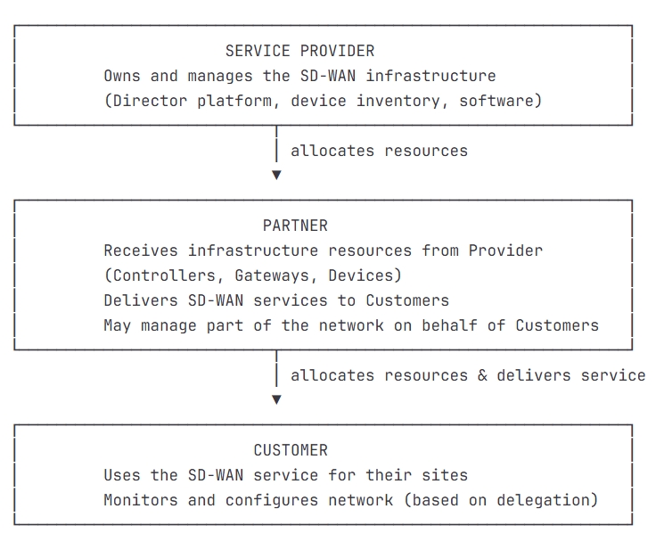 |
As a customer, you have access to a Customer Portal that gives you clear visibility into your network status, traffic, and application performance, along with easy‑to‑use tools to configure and manage your SD-WAN network. To keep the platform secure, reliable, and scalable as your network grows, the Director uses lightweight, stateless controllers that communicate efficiently with SD-WAN and Edge devices.
Once you’re logged in, you can use the Customer Portal as your main workspace to manage and interact with your SD-WAN network.
The home page presents a consolidated, real‑time view of your network, helping you quickly assess overall health and identify any issues that may require attention. Key information such as site availability, overlay performance, device status, and traffic usage is displayed in a clear and actionable way. A map view complements this by showing the geographic distribution of your sites.
Navigation is organized around the main components of your network. From the menu, you can access sections dedicated to sites, overlays, traffic policies, devices, firewall configuration, and monitoring. Each section provides focused tools to either observe network behavior or make targeted configuration changes.
The actions available to you depend on your assigned role. At a basic level, you may only monitor status, analytics, and alarms. With additional permissions, you can progressively manage overlays and traffic policies, configure LAN settings at the site level, and, if fully authorized, modify WAN configurations. This tiered access ensures that sensitive configuration changes remain controlled while still allowing you to handle day‑to‑day operational tasks efficiently.
In some cases, your Partner may take responsibility for advanced configurations, while you use the portal primarily for visibility and routine management.
To help you understand how responsibilities are assigned in the 3‑tier model, the table below breaks down each solution component, its role, and its managing team.
Component | What It Does | Who Manages It |
|---|---|---|
Director | Centralized orchestration platform with web portals and REST API | Service Provider |
Controller | Control plane services (monitoring, key management, DNS load-balancer, NTP time-server) | Partner |
Gateway (optional) | VPN concentrator for connecting to external networks (hosted data center or MPLS networks) | Partner |
Edge | Ekinops OneOS6 router installed at your branch offices | Assigned to your sites |
Customer Portal | Your web interface for monitoring and configuration | You (Customer) |
To simplify configuration across all your sites, the SD-WAN solution relies on three key concepts: labels, overlays, and traffic. Together, they form a logical model that separates what your traffic is, where it should go, and how it should be transported across the network.
Labels provide an abstraction layer over your physical infrastructure by assigning logical names to router interfaces. Instead of referring to specific ports, which may differ from one site to another, you work with consistent identifiers that represent their role in the network, such as LAN segments or WAN access types. This approach allows configurations to be defined once and applied uniformly, regardless of hardware variations or site‑specific constraints, greatly simplifying large-scale deployments and ongoing operations.
Traffic describe how network flows are identified and categorized. Each traffic is defined through a set of classification rules based on criteria such as IP addressing, protocols, ports, or applications. This enables you to translate business intent into technical definitions, for example, distinguishing critical business applications from general internet browsing. By structuring your traffic in this way, you create a clear and reusable framework that can be used to apply routing decisions, performance policies, and prioritization across the network.
Overlays then define how these identified traffic are actually transported. They represent the logical paths that traffic follows from source to destination, independent of the underlying physical connectivity. An overlay determines whether a given traffic is sent directly to the internet or routed through private connectivity between sites or data centers, and how it uses the available WAN links. It also governs behaviors such as path selection, load balancing, and priority handling, ensuring that each type of traffic is delivered according to its requirements.
By combining labels, traffic, and overlays, you can express networking intent in a structured and consistent way: labels define where traffic enters and exits, traffic define what the traffic is, and overlays define how it moves through the network. This modular approach not only reduces configuration complexity but also makes policies easier to understand, maintain, and evolve over time.
Learn more
You can find more information about these key concepts and other Configuration Objects in the related section.
How it all connects
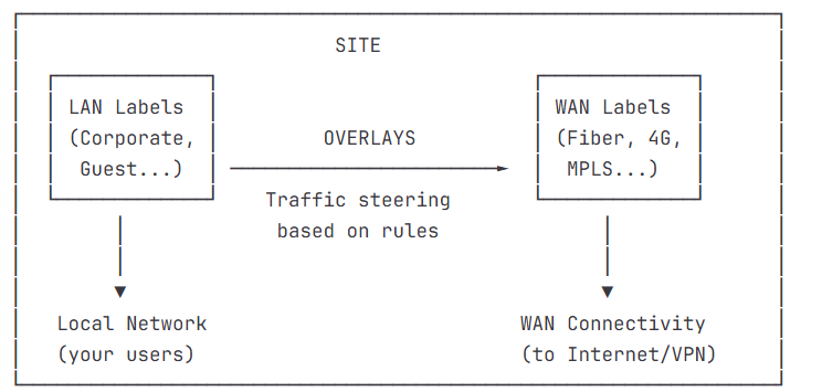
To understand how traffic is identified and handled, it’s important to see how Labels and Overlays work together:
 |
Here are two examples:
Internet Access Traffic Flow: when a user on the LAN‑Corporate network accesses Microsoft Office 365, the traffic matches a policy rule associated with an Internet overlay configured for local egress. The traffic is then routed directly to the Internet through the WAN‑Fiber connection.
Private Application Traffic Flow: when a user on the LAN‑Corporate network accesses the ERP server hosted at headquarters, the traffic matches a rule assigned to a VPN overlay using a hub‑and-spoke topology. The traffic is encrypted and forwarded through a VPN tunnel to the hub site.
Steps to get started with SD-WAN
Here are the steps to get started:
Log in to the Customer Portal with the credentials provided by your Partner. After you log in, you can access the areas available to your account.
Follow these steps to log in for the first time:
Change the initial password provided by your Partner. When you log in to the Director for the first time, you are prompted to create a new password.
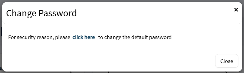
On the Change Password page, enter your current password, enter and confirm your new password.
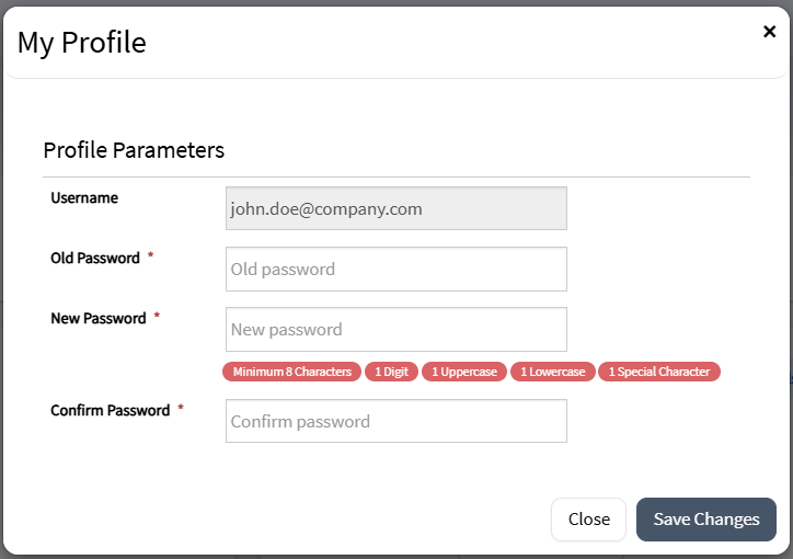
Click Save Changes.
After you change your password, you can log in using one of the following methods:
Language selection
On the login page, click the language selector to choose your preferred language: English or French. After you select a language, the login page text is displayed in the selected language.
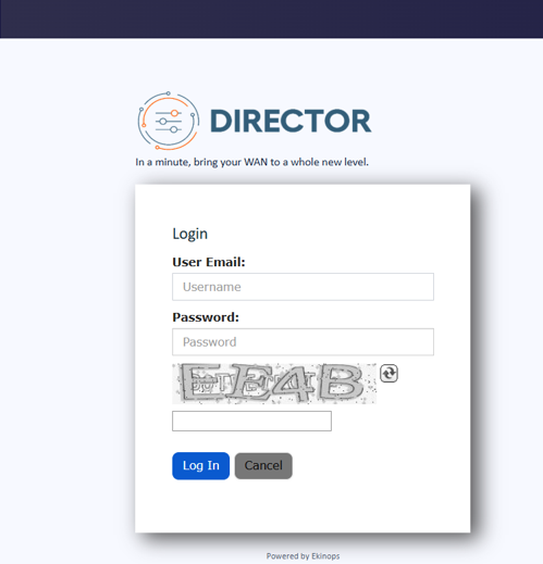
Use this method if your account is managed locally in the Customer Portal. Sign in with your email address and password. After your login is successful, the Customer Dashboard opens.
For security reasons, your session expires automatically after a period of inactivity.
Enter the following information:
Email
The email address associated with your user account.
Password
The password for your user account.
Captcha
If your service provider enabled CAPTCHA during SD-WAN installation, you must complete a verification step before you can log in.
 |
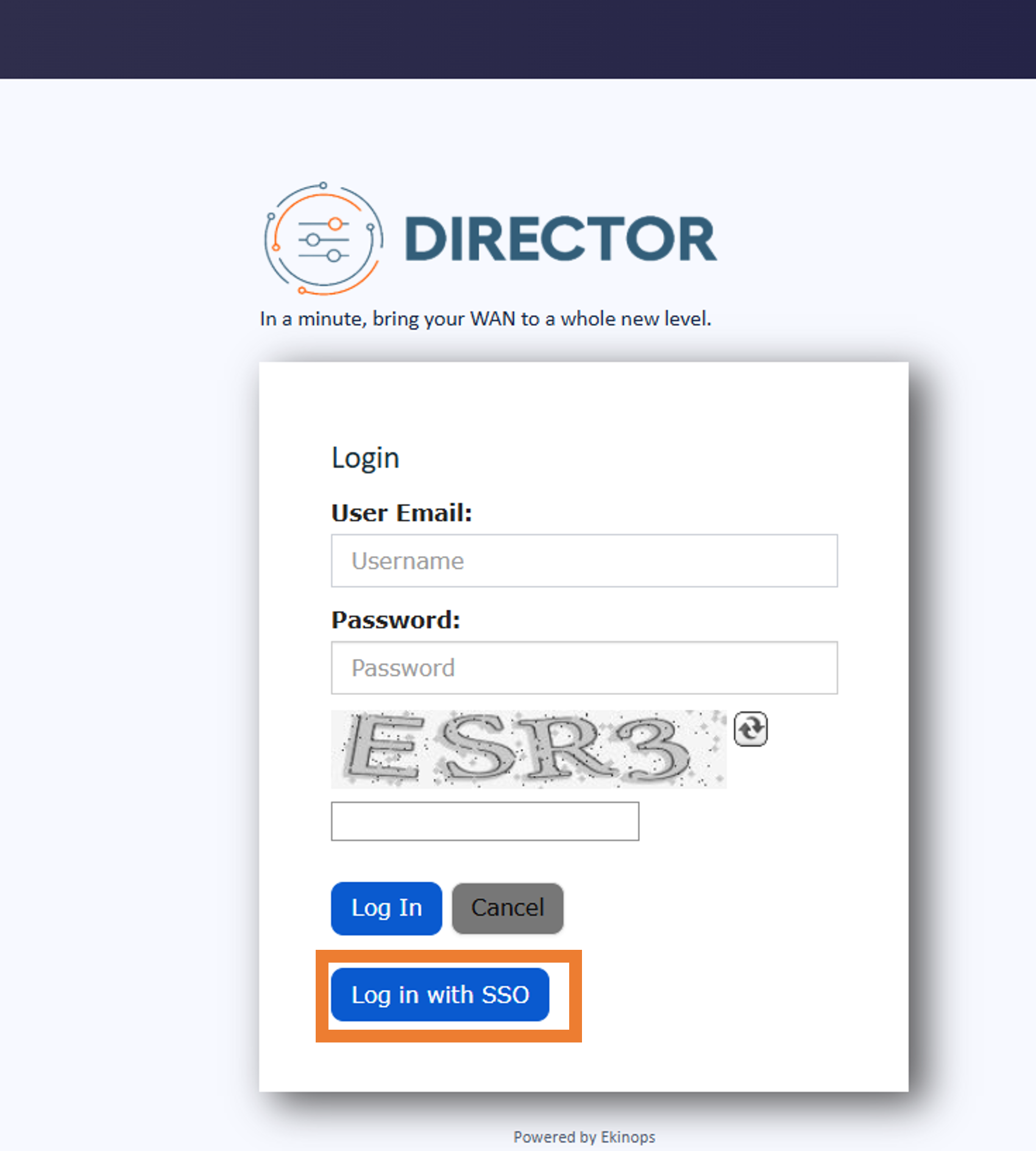
Use this method to log in with Single Sign-On (SSO). In this case, the service provider manages user accounts and credentials for portal access.
Click Log In with SSO to continue. After your login is successful, the Customer Dashboard opens.
 |
SSO availability
The Log In with SSO button is available only when at least one Identity Provider (IdP) is configured and enabled by Service Provider.
This topic helps you set up your first enterprise SD-WAN network. It walks you through the main configuration steps, from preparing the network design to creating traffic rules, overlays, and sites.
It is intended for administrators who are configuring SD-WAN for the first time.
Configuration Overview
You configure your SD-WAN network in a logical order. Each step builds on the previous one.
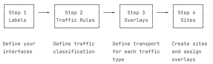 |
The workflow includes the following steps:
Create interface labels to identify the types of WAN connections used in your SD-WAN network, such as fiber, 4G, primary link, backup link
Define traffic rules to control how application traffic is classified and forwarded across the SD-WAN network. Traffic rules help determine which overlays are used based on business needs such as performance, availability, or security.
Create overlays to define the logical paths that connect your sites. Overlays use the interface labels and traffic rules you configured earlier to determine how traffic flows between locations.
Create Sites and Assign Overlays
Create your SD-WAN sites and assign the appropriate overlays to each site. This final step connects your locations to the SD-WAN network and enables traffic to be routed according to the overlays and policies you defined.
Order exception — VPN with a hub site
If the hub is a site rather than a gateway or gateway cluster, create and the hub site in the Director save before you create the VPN overlay (Hub & Spoke).
The VPN overlay requires a valid hub site before it can be configured. Spoke sites can be created and attached after the overlay is created.
When deploying a new hub location, complete the step Create Sites and Assign Overlays step for the hub site before moving on to Create Overlays for the VPN overlay design.
After completing these steps, your enterprise SD-WAN network will have the basic configuration needed to connect sites, steer traffic, and apply consistent network behavior across your organization. The following sections guide you through each step in order.
Interface labels let you use the same logical names for LAN and WAN interfaces across all sites, even when the underlying hardware is different.
For more information about how LAN and WAN labels are used, see Labels in Configuration Objects.
To configure your labels, follow these steps.
Go to Objects > Labels
Click + Add label (
 ) in the top‑right corner.
The New label window opens.
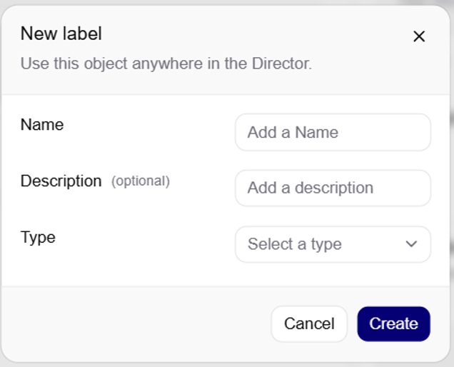
Select a label type from the drop-down list.
LAN Labels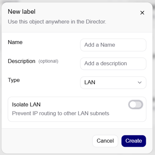
Define LAN labels based on your enterprise network segmentation, such as IP subnets or VLANs (Virtual Local Area Networks).
LAN isolation (Optional)
You can enable LAN Isolation to prevent traffic between this LAN interface and other LAN interfaces on the same site without using firewall rules.
Option A: Simple Numbering
Use this option for a simple naming approach based on the maximum number of LAN links per site.
Label Name
Description
LAN1
Primary LAN segment
LAN2
Secondary LAN segment
Option B: By Purpose/Segment
Use this option when you want to identify each LAN by its purpose.
Label Name
Description
Typical Use
LAN-Corporate
Corporate user network
Employee workstations
LAN-Guest
Guest WiFi network
Visitor access
LAN-VoIP
Voice over IP network
IP phones
LAN-Camera
Surveillance network
Security cameras
LAN-IoT
IoT devices
Sensors, building automation
WAN Labels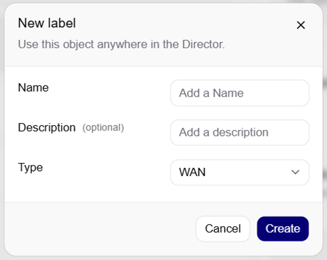
Define WAN labels based on your enterprise WAN connectivity strategy.
Option A: Simple Numbering
Use this option when you want a simple naming approach based on the maximum number of WAN links per site.
Label Name
Description
WAN1
Primary WAN connection
WAN2
Secondary WAN connection
WAN3
Tertiary WAN connection
Option B: By Connection Type
Use this option when you want to identify the WAN technology used at each site. You can add label descriptions for additional context.
Note: If you have multiple connections of the same type (e.g., 2 fiber links), create numbered variants: WAN-Fiber1, WAN-Fiber2.
Label Name
Description
WAN-Fiber
Fiber connection
WAN-Fiber2
Second fiber connection (if applicable)
WAN-DSL
xDSL connection
WAN-4G
Embedded 4G cellular
WAN-4G-Ext
External 4G/5G router
WAN-MRU
External 5G modem (Ekinops MRU)
Enter a name for the Label.
Name Format
The name can include letters, numbers, and underscores (_). Spaces are not allowed.
(optional) Add a short description.
Click Create (
 ) after you enter the required details.
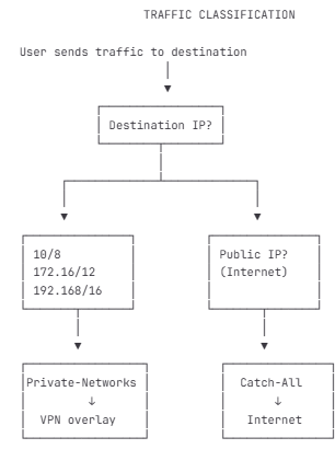
Traffic Rules, formerly called Rule Groups, define how enterprise traffic is classified. Each Traffic Rule contains one or more rules that identify traffic based on criteria such as destination IP address, source IP address, port, protocol, or application.
For a first configuration, we recommend classifying traffic by destination IP address. This approach is simple, predictable, and works well for most enterprise deployments.
For most enterprises, traffic can be classified into two fundamental categories based on destination:
Traffic Type | IP Destination | Overlay type |
|---|---|---|
Private traffic | Private network ( | VPN |
Internet traffic | Any | Internet |
How Traffic Rules are evaluated
Traffic Rules are evaluated in the context of the ingress LAN interface. The ingress LAN interface is the user-side LAN interface on which the packet enters the Router.
The rules inside a Traffic Rule use OR logic (e.g., Rule 1 or Rule 2). A flow matches the Traffic Rule when it matches at least one rule. The flow does not need to match every rule in the Traffic Rule.
Best Practices
Before you create Traffic Rules, review these best practices:
Start simple: begin with the two basic Traffic Rules: Private-Networks and Catch-All. Add more specific rules only when needed.
Work from business intent: ask the customer or operational owner to identify which traffic is important, restricted, or business-critical before you define Traffic Rules. These decisions determine the rule criteria, how Traffic Rules are split, and which overlays, WAN labels, QoS settings, or link-sharing policies they use.
For example, a line-of-business application might need to be prioritized, streaming traffic might need to be denied on 4G or routed only through a fixed-cost WAN link, and collaboration applications might need to remain available during congestion or link failure. Translate each business goal into one or more concrete Traffic Rules and associated WAN link traffic policies. Do not create Traffic Rules without a clear business objective.
Use IP-based rules for internal traffic: IP-based matching is typically more reliable than application detection for site-to-site traffic.
Use application-based rules for cloud services: SD-WAN uses Olfeo technology, and internet traffic is best identified by application detection.
Remember that overlay order matters: Assign more specific Traffic Policies to overlays with higher priority.
To create a Traffic Rule, complete the following steps.
Go to SD-WAN > Network > Traffic.
Click + Add traffic (
 ) in the upper-right corner of the Traffic list table.
The Add Traffic window opens.
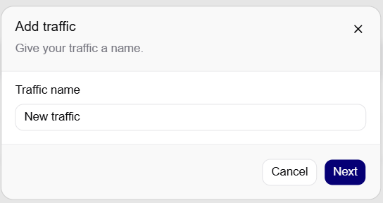
Name the new traffic.
Click Next in the lower-right corner of the window.
Click the + Add rule button (
 ) in the upper-right corner of your screen or in the Rules section.
Note: Repeat this step to add as many rules as needed.
Click the Add criteria button (
 )
Select the criterion(s) you want to use from the drop-down list.
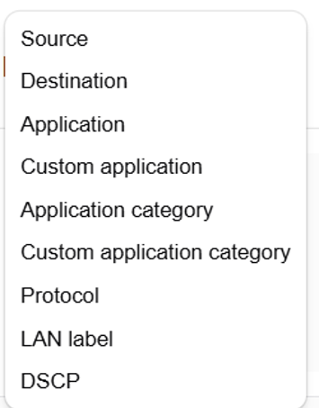
Enter the information associated with the selected criteria.
Source IP / CIDR: select one or more source IP address or subnet in CIDR notation.
Destination (IP / CIDR): select one or more destination IP address or subnet in CIDR notation.
Application Category/Name: select one or more application categories and application names from the dropdown list.
Custom application: choose one or more app names from the options provided.
Application category: select one or more application categories.
Custom application category: select one or more user-created application categories and application names from the dropdown list.
Protocol (Mandatory): keep the default value, IP, or select another protocol from the dropdown list: TCP, UDP, ICMP.
LAN Label: select one or more LAN labels that the traffic must match. The dropdown list contains the LAN labels defined for the current customer.
DSCP: select one or more values from the dropdown list.
Click Create in the lower-right corner of the window.
For most enterprises, traffic can be classified into two fundamental categories based on destination:
Traffic Type | Destination | Overlay type |
|---|---|---|
Private traffic | Private network ( | VPN |
Internet traffic | Any | Internet |
Traffic Policy 1 — Private-Networks
This Traffic Policy matches traffic going to private destinations (other sites or the data center).
Name |
|
|---|---|
Purpose | Site-to-site and site-to-data center traffic |
Overlay | VPN overlay (Hub & Spoke) |
Rule # | Source | Destination | Description |
|---|---|---|---|
1 |
|
| Traffic to 10.x.x.x |
2 |
|
| Traffic to 172.16-31.x.x |
3 |
|
| Traffic to 192.168.x.x |
Use one rule for one private range
If your enterprise uses a single private IP range, such as 10.0.0.0/8, you only need to create one rule for that range.
Traffic Policy 2 — Catch-All
This Traffic Policy matches all remaining traffic — anything going to the internet.
Name |
|
|---|---|
Purpose | Internet access |
Overlay | Internet (local or cloud egress) |
Rule # | Source | Destination | Description |
|---|---|---|---|
1 |
|
| All other traffic |
Place catch-all rules last
This rule catches all traffic not matched by more specific Traffic Policies. Assign it to an overlay with the lowest priority.
How it works
Overlays are configuration objects that define the transport paths available for traffic in the SD-WAN network. An overlay determines how traffic can flow from a site LAN to its destination across one or more WAN transports.
After an overlay is created, it can be assigned to sites and used by traffic policies. When you assign an overlay to a site, that site can use the transport paths and policy behavior defined by the overlay.
Within each overlay, you can reference multiple traffic rules. Each traffic rule can define its own Quality of Service (QoS) and link-sharing behavior, including link-sharing policy and QoS weight.
Two types of overlay are available: VPN and Internet.
Internet: carries traffic to the public internet. Use this overlay type for cloud applications, web browsing, or direct internet access.
VPN: carries private traffic over encrypted IPsec tunnels. Use this overlay type for site-to-site connectivity, LAN-to-data center traffic, or external networks like MPLS (via a gateway or gateway cluster provided by Partner).
To learn more about overlays, see Configuration Objects.
Classification order and QoS weight are different
As you assign overlays and configure traffic policies in this step, bear in mind that classification order and QoS weight serve different purposes:
Classification order determines which overlay handles the traffic. It is controlled by the order of overlays assigned to the site. Overlays are evaluated from top to bottom, and the first overlay whose traffic policy matches the traffic handles it. Place specific overlays first and general overlays last.
QoS weight, also called Link Sharing Weight determines how bandwidth is allocated when WAN links are congested. It is configured in the traffic policy settings on the overlay. When multiple traffic types share the same WAN link, a higher weight gives the traffic class more bandwidth.
Choose the overlay type that you want to create, then follow the corresponding procedure.
Go to SD-WAN > Network > Overlays.
Click + Add overlay (
 ) in the top‑right corner.
The New overlay window opens.
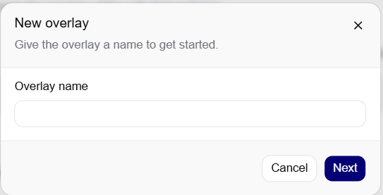
Name the new Overlay.
Click Next.
In the Overlay general parameters section, enter the following information:
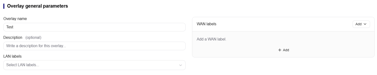
Overlay Name: enter a name for the overlay.
Description (optional): add a short description.
LAN Labels: select one or more LAN labels from the dropdown list.
WAN Labels: select one or more WAN labels from the dropdown list.
Number Of Sites And Gateways: choose the number of sites and gateways that will be part of your Overlay (between 6-16382).
In the Overlay usage section:
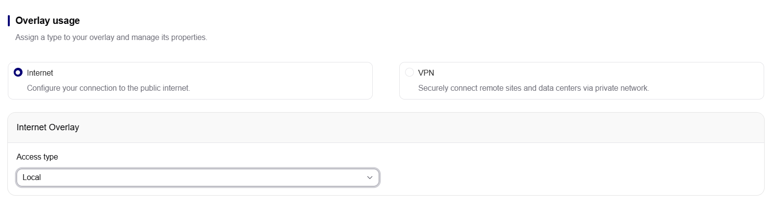
Select the Internet option.

From the Access Type drop-down list, select either Local or Cloud.

Breakout type
Breakout type determines how traffic from the LAN reaches the internet.
Local Breakout: Routes internet traffic directly through the WAN underlay. Use for fast access to trusted applications.
Cloud Breakout: Routes internet traffic through a VPN tunnel to a web gateway. Use for secured internet access through a third-party security service.
(optional) If you selected the Cloud access type in the previous step:
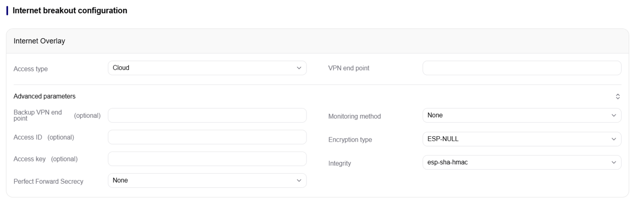
Enter the VPN access point by entering the IP address or FQDN of the primary VPN access point.
Click Advanced Settings, and enter the following information:
Backup VPN Endpoint (optional): enter the IP address or FQDN (fully qualified domain name) of the backup VPN endpoint. The backup endpoint is used if the primary VPN endpoint becomes unavailable.
Monitoring Method: select the method used to monitor the VPN tunnel status.
Access ID (optional): enter the access identifier, if required by the VPN endpoint.
Access Key (optional): enter the access key, if required by the VPN endpoint.
Encryption: select the encryption algorithm used to protect VPN traffic.
Integrity: select the integrity algorithm used to validate VPN traffic.
Perfect Forward Secrecy: select the PFS (Perfect Forward Secrecy) setting for the VPN tunnel.
In the Traffic steering section, enter the following information:

Click the + Add policy button (
 ).
Enter the following information:
Traffic Rule: select the traffic rule classification that applies to this overlay.
Strategy (formerly Link Sharing Policy): Select the desired routing strategy from the drop-down list. "Fastest" uses the WAN link with the best performance; "Performance" uses WAN links that meet the defined performance target; and "Available" distributes traffic across the available WAN links.
Performance
If you select the Performance goal, you must specify a target value.
WAN DSCP (optional): Enter a DSCP value (1–63) to prioritize WAN traffic. This setting should be used only when provided by your telecom operator. If no instructions are given, leave the field empty.
Primary WANs: Select the WANs that will carry traffic on a priority basis.
Secondary WANs (optional): Select the WANs to be used as supplements or backups for the primary WANs.
Link Sharing Weight: enter the QoS bandwidth percentage for this traffic.
Multiple Overlay Traffic Policy
Each overlay can reference multiple traffic rules, each with different QoS settings.
In this example, all four traffic rules are attached to the same overlay (Overlay-Internet) and use the same transport path, Local Breakout.
However, LAN user traffic may use a different WAN link depending on the selected traffic policy and WAN health metrics, such as latency, packet loss, and jitter.
Traffic Policy
Link Sharing Weight
Link Sharing Policy
WAN Links
Collaborative-CloudApp
4
Fastest
ERP-CloudApp
4
Performance (lower latency)
WAN1, WAN2
Streaming
1
Available
WAN1 only
Catch-All
2
Available
WAN1, WAN2
For additional use cases, see the examples for Single Internet Overlay with Multiple Traffic Policies and Multiple Internet Overlays for Different Paths.
Click Add (
 ) in the lower-right corner of the window.
Use cases
The examples below continue from step 4 of the procedure and use the Overlay-Internet example table with the following traffic rules: Collaborative-CloudApp, ERP-CloudApp, Streaming, and Catch-All.
Use this option when all internet traffic uses the same egress type, such as Local Breakout, but different traffic classes require different link-sharing policies and weights.
For example, the same Internet overlay can include multiple traffic policies for Collaborative-CloudApp, ERP-CloudApp, Streaming, and Catch-All traffic. Each policy can use a different link-sharing behavior, such as Fastest, Performance, or Available, while still using the same overlay and egress type.
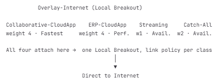 |
Schema notes: “Perf.” means Performance link-sharing policy. “Avail.” means Available link-sharing policy. The schema uses the same columns as the example table.
Use this option when different traffic classes require different internet paths. For example, some traffic classes can use direct internet access, while others, or a catch-all rule, can be routed through a cloud security web gateway.
In this example, the same four traffic policies are split across two Internet overlays. When assigning the overlays to a site, list the more specific overlay first so that traffic is matched before it reaches the more general overlay.
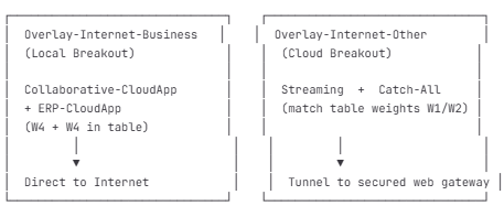 |
Schema notes: This split is an example only. Place traffic policies on the local or cloud overlay based on your business intent, such as sending Streaming and Catch-All traffic through inspection while keeping Collaborative-CloudApp and ERP-CloudApp on direct breakout.
Go to SD-WAN > Network > Overlays.
Click + Add overlay (
) in the top‑right corner.The New overlay window opens.
In the Overlay general parameters section, enter the following information:
Overlay Name: enter a name for the overlay.
WAN Labels: select one or more WAN labels from the dropdown list.
LAN Labels: select one or more LAN labels from the dropdown list.
Description (optional): add a short description.
In the Overlay Usage section, enter the following information:
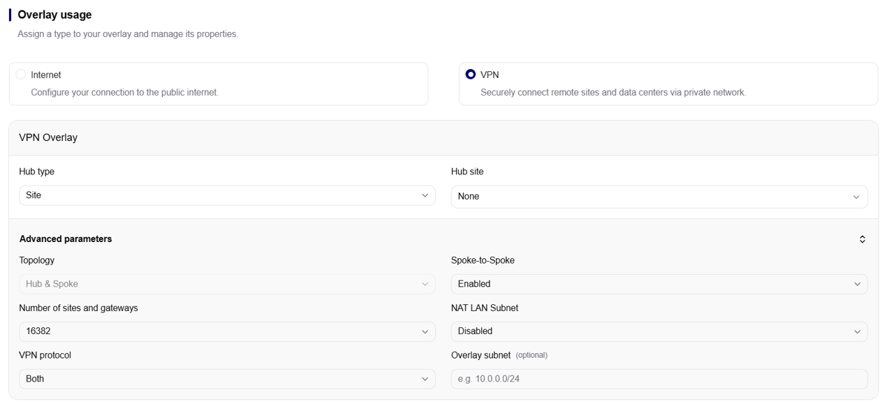
Spoke-To-Spoke: check this option to allow spoke sites to communicate directly with each other instead of routing all spoke-to-spoke traffic through the hub.
Select Hub Type: select the type of hub used by the Hub & Spoke topology.
Hub types
Hub-and-spoke topology routes traffic between private sites through encrypted IPsec tunnels by using a central hub
Site: one of your sites acts as the hub. Use this option when your own data center hosts the servers or applications that branch sites need to reach. Before selecting this option, refer to Important: Hub site before VPN overlay.
Hub Site: select the site that acts as the central hub for the Hub & Spoke VPN overlay. Traffic from spoke sites is routed through this hub site.
Backup Hub Site (legacy): select the site that acts as the backup hub. The backup hub is used if the primary hub site becomes unavailable.
Use only with legacy Hub HA
Select this option only when maintaining an existing legacy Hub HA deployment with a backup hub. This option is not available for Single Edge or Dual Edge sites.
Number Of Sites And Gateways: choose the number of sites and gateways that will be part of your Overlay (between 6-16382).
NAT LAN Subnet: enter the translated LAN subnet to use when NAT (Network Address Translation) is required for LAN traffic in this overlay.
VPN Protocol: select the VPN protocol (IKE, TINA, Both) used to establish the encrypted tunnel for this overlay.
Overlay Subnet (Optional): enter the subnet used for overlay tunnel addressing, if you want to define it manually. Leave this field empty to use the default or automatically assigned overlay subnet.
In the Traffic steering section, enter the following information:
Traffic Rule: select the traffic rule classification that applies to this overlay.
WAN DSCP (optional): Enter a DSCP value (1–63) to prioritize WAN traffic. This setting should be used only when provided by your telecom operator. If no instructions are given, leave the field empty.
Link Sharing Weight: enter the QoS bandwidth percentage for this traffic.
Strategy (Link Sharing Policy): Select the desired routing strategy from the drop-down list. "Fastest" uses the WAN link with the best performance; "Performance" uses WAN links that meet the defined performance target; and "Available" distributes traffic across the available WAN links.
Multiple Overlay Traffic Policy
Each overlay can reference multiple traffic rules, each with different QoS settings.
In this example, all four traffic rules use the same VPN overlay (Overlay-VPN) and follow the same logical transport path: private traffic is carried over the VPN overlay (hub-and-spoke topology to the hub Site or Gateway), not through local Internet egress (Local Breakout).
However, depending on the associated traffic rule and the Strategy configured on the overlay, traffic from users on the local area network (LAN) can use a different WAN link at the site (WAN1 or WAN2). Selection is based on WAN link health metrics such as latency, packet loss, and jitter.
Traffic Policy
Link Sharing Weight
Strategy
WAN Links
Enterprise-Business-Apps
4
Fastest
Enterprise-VoIP-Network
4
Performance (lowerst latency)
WAN1, WAN2
Enterprise-Data-Backup
2
Available
WAN2 only
Enterprise-Other
2
Available
WAN1, WAN2
Click Add (
) in the lower-right corner of the window.
Use Case
You can create multiple VPN overlays when traffic must reach different private destinations.
In this scenario:
Data center: your headquarters hosts enterprise applications and file servers on subnet
10.0.0.0/8.MPLS network: legacy sites are reachable through a Partner MPLS service on subnet
172.16.0.0/12.
In this scenario, you can create one VPN overlay for data center traffic and another VPN overlay for MPLS traffic.
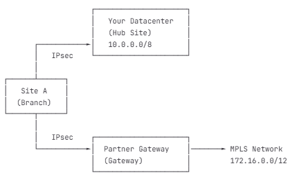 |
Overlay | Hub Type | Hub | Traffic Rule |
|---|---|---|---|
Overlay-Datacenter | Site | Site-HQ (your data center) | Traffic-Datacenter |
Overlay-MPLS | Gateway | Partner's Gateway | Traffic-MPLS |
Sites represent your physical locations. Creating a site connects a Router device to your SD-WAN network and defines how traffic flows for that location.
Hub site for VPN overlays
If a VPN overlay uses Hub type: Site. You must create the hub site before you create the VPN overlay. For more information, see the order exception in Configuration Overview.
For greenfield deployments, plan to bring up the hub site first.
To create a site, you'll need to:
Select the OneOS6 router for the site.
Step B: configure LAN and WAN Interfaces
Configure the IP addresses and assign the appropriate labels.
Assign overlays to control how traffic is routed for the site.
Each site must have a OneOS6 router, also known as customer premises equipment (CPE), assigned to it.
Available devices
Available devices are routers assigned to your customer account by your Partner and not yet used by another site.
Go to SD-WAN > Sites
Click Add (
 ) in the top‑right corner.
Choose the site type that you want to create.
Single Edge: select this option for a standard branch office with one Router device.
Dual Edge: select this option for a site that requires high availability with two Router devices and redundancy using VRRP (Virtual Router Redundancy Protocol).
Hub HA (legacy): Select this option only for data center hub sites that use multiple OneOS6 devices as VPN concentrators for Spoke sites. This site type does not support user traffic from its LAN.
Limited use case
Hub HA is intended only for existing legacy deployments. For new data center hub sites, use the current recommended site type (Single or Dual Edge).
The Add Site window opens.
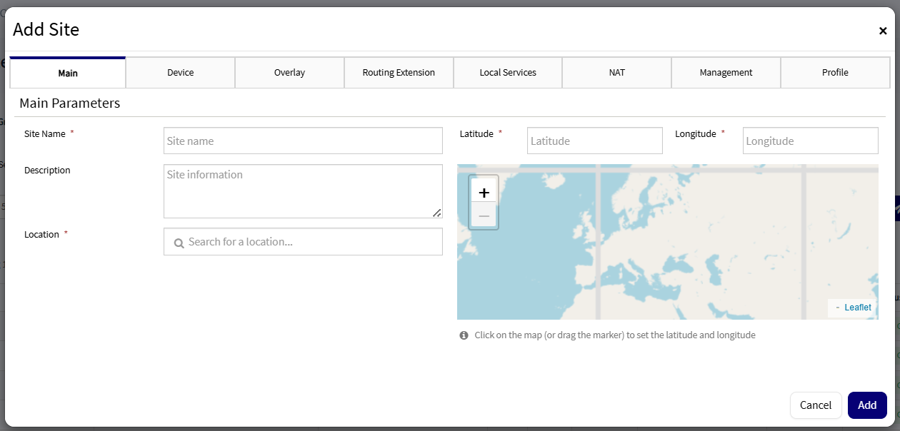
On the General tab, enter the following information:
Site name: a unique name for the site. Use letters, numbers, and underscores (_). Spaces are not allowed.
Description (optional): an optional description for the site.
Location: the geographic location of the site. The latitude and longitude are filled in automatically.
On the Router tab, in the Router Settings section, fill in the following fields:
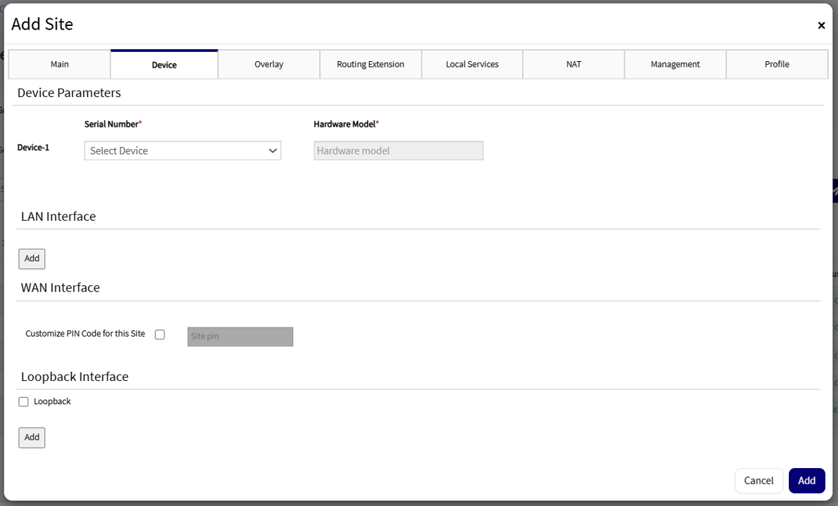
Serial number: select the device serial number from the drop-down list.
Hardware type: this field is filled in automatically based on the selected device and is read-only.
Before you continue
Keep the Add Site window open. You will complete the next step in this window.
In this step, you define which router interfaces participate in the SD-WAN by assigning labels and IP addresses.
Labels create a logical representation of router interfaces across your sites. Instead of configuring overlays and traffic policies with physical interface names, you use labels to identify the role of each interface, such as LAN-Corporate, WAN-Fiber, or WAN-LTE.
This abstraction makes the configuration easier to reuse across sites, even when sites use different router models or different physical interface names.
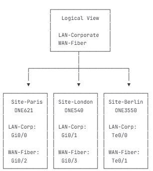 |
Benefit | Description |
|---|---|
Consistency | Use the same label names, such as LAN-Corporate or WAN-Fiber, across all sites. |
Simplicity | Overlays and traffic policies reference labels instead of physical interfaces. |
Flexibility | Different router models can be used at different sites without changing the logical design. |
Scalability | Add new sites without changing overlay or policy configuration. |
To configure the local LAN, on the Router tab, in the LAN Interface section:
In the LAN Interface section, click Add (
 ).
Enter the following information for each LAN interface:
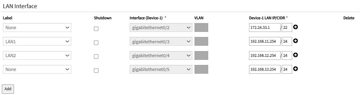
Label: Select a local network label (for example, LAN-Corporate).
Disable (optional): Disable the Label.
Interface (Router-x): Select the physical interface on this specific router.
VLAN (optional): enter the VLAN ID if the interface uses tagged traffic. Valid range: 1–4094.
Router-x IP / LAN CIDR: Enter the local network's IP address and subnet mask.
After you configure the LAN interfaces, configure the WAN interfaces that connect the site to its transport networks.
To configure the WAN (Wide Area Network), on the Router tab, in the WAN Interface section:
Before you continue
Keep the Add Site window open. You will complete the next step in this window.
In the WAN Interface section, click Add (
).Enter the following information:

DHCP (Dynamic Host Configuration Protocol) (optional): enable if IP is assigned automatically by the ISP
IP Address/CIDR: enter the WAN IP address (if not DHCP)
Public IP (optional): enter the public IP address if it is different from the interface IP address, for example, when Network Address Translation (NAT) is performed after the router.
Gateway: enter the default gateway IP address for the WAN interface.
NAT (optional): Disable network address translation (NAT) on the WAN interface.
Label: select a WAN label (e.g., WAN-Fiber)
Interface: select the physical interface on this specific router
Upload Bandwidth (optional): enter the upstream link speed in kbps. This value is used for QoS.
Download Bandwidth (optional): enter the downstream link speed in kbps. This value is used for QoS.
MTU (optional): Specify the maximum size of packets transmitted over the WAN interface. The recommended value depends on the type of connection used.
Overlays define the virtual network paths that connect this site to other sites in the SD-WAN network. The overlays selected for the site determine which traffic paths are available and how traffic is routed according to the traffic policies defined for each overlay.
To assign Overlays to the site, go to the Overlay tab:
In the Overlay Selection section:
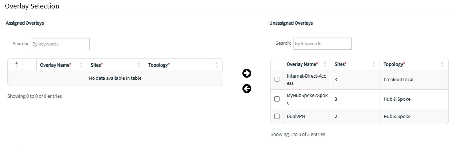
Select the overlays from the Unassigned Overlays list, then click the left-pointing arrow to move the overlays to the Assigned Overlays list.
In the Assigned Overlays list, drag the overlays using the dedicated icon (
 ) to arrange them from the most specific to the least specific.
Overlay order matters
Traffic is matched from top to bottom, and the first matching overlay handles the traffic.
Click Add (
) in the lower-right corner of the Add Site window.
Congratulations!
You have successfully set up your first SD-WAN enterprise network.
Next Steps
Once your first enterprise SD-WAN network is set-up, you can move on to the following steps to continue your configuration:
Explore the Dashboard to familiarize yourself with site and overlay status
Review Your Sites to understand your current site configurations
Check Traffic Analytics to see which applications consume your bandwidth
Learn Overlay Management to understand how to adjust Traffic Policies and overlay QoS