LAN connectivity
On the LAN side, SD-WAN routers support several connectivity options for connecting users, devices, and local networks
The following LAN connectivity types are supported:
Physical network interfaces using electrical RJ45 or optical SFP media. Depending on the hardware model, Ethernet connectivity is provided through
gigabitethernetortengigeinterfaces.A group of Ethernet interfaces operating as a single switching domain, allowing connected devices to communicate at Layer 2.
Virtual LANs (VLANs) using IEEE 802.1Q tagging to logically separate traffic on the same physical network infrastructure.
Wireless LAN connectivity, available on single-edge site deployments only.
The LAN connectivity options available depend on the hardware model and enabled features.
LAN type | Interface name |
|---|---|
Ethernet interface | gigabitethernet slot/port tengige slot/port |
Ethernet switch | bvi bridge-group |
Ethernet VLAN | gigabitethernet slot/port.vlan tengige slot/port.vlan bvi bridge-group.vlan |
Wireless LAN | wifi1 / wifi2 / wifi3 / wifi4 |
Wi-Fi/Ethernet bridge | bvi bridge-group(.vlan) |
Ethernet
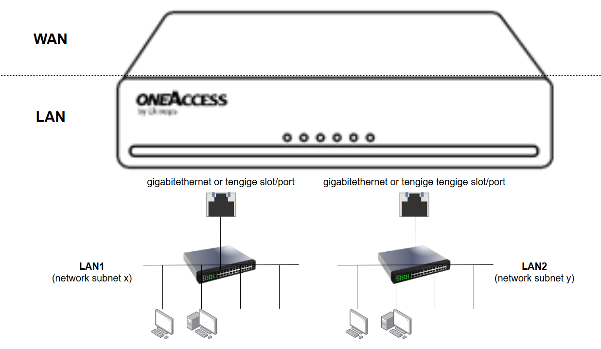
LAN subnets can be deployed on gigabitethernet (1 Gbps) or tengige (10 Gbps) interfaces.
In the simplest topology, user devices are connected directly to an Ethernet interface on the SD-WAN router.
However, the most common deployment model is to connect an Ethernet switch between the SD-WAN router and the user devices. This allows multiple devices to access the same subnet and simplifies network expansion.
The following design illustrates common Ethernet deployment topologies.
 |
VLAN (virtual LAN)
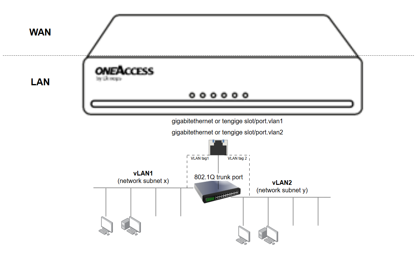
VLAN technology allows multiple LAN subnets to share the same Ethernet interface while remaining logically isolated from each other.
In this deployment model, the SD-WAN router is typically connected to an external Ethernet switch through an IEEE 802.1Q trunk link.
Each VLAN is identified by a VLAN tag. The SD-WAN router adds the appropriate VLAN tag to outgoing traffic and processes only the traffic associated with the configured VLANs.
The Ethernet switch uses these VLAN tags to forward traffic to the appropriate access ports, allowing multiple isolated LAN segments to coexist on the same physical infrastructure.
This approach is commonly used to separate different categories of users or devices, such as corporate users, guest networks, servers, or voice services.
The following design illustrates a VLAN-based LAN topology.
 |
Switch
By default, Ethernet interfaces on the SD-WAN router operate as routed interfaces, meaning that each interface belongs to a separate Layer 3 network.
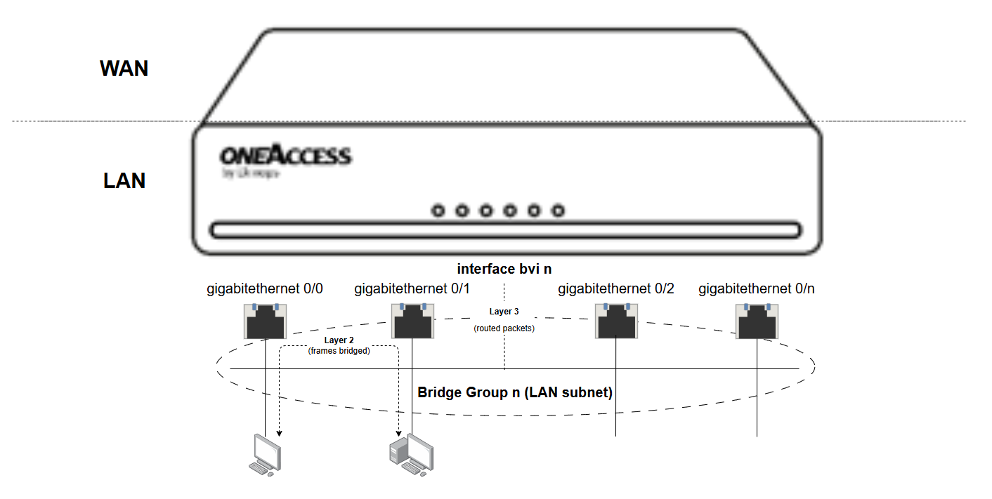
Alternatively, multiple Ethernet interfaces can be grouped together to form a switching domain, also known as a bridge group. In this mode, the router behaves like an Ethernet switch and forwards Ethernet frames between the interfaces that belong to the same bridge group.
This deployment model is useful when multiple ports must provide access to the same LAN subnet.
To forward traffic efficiently, the switching function maintains a table of MAC addresses associated with each port. When an Ethernet frame is received, the router uses the destination MAC address to determine the port on which the destination device is located and forwards the frame accordingly.
When physical interfaces are grouped into a bridge group, the router creates a Bridge Virtual Interface (BVI). The BVI acts as the Layer 3 gateway for the bridged network and hosts the IP address associated with the LAN subnet.
The following design illustrates an Ethernet switch topology.
 |
Combining Switching and VLANs
VLANs can also be configured on a BVI interface. This allows multiple VLAN-based LAN subnets to share the same physical switch ports while remaining logically isolated from each other.
For example, separate subnets such as bvi.vlan10 and bvi.vlan20 can coexist on the same Ethernet infrastructure while serving different groups of users or devices.
Wireless LAN
On SD-WAN routers equipped with a Wireless LAN controller, IEEE 802.11 Wi-Fi connectivity is available, allowing the router to operate as a Wireless LAN Access Point (WLAN AP).
The wireless controller supports up to four Wi-Fi networks, represented in the Customer Portal by the interfaces wifi1, wifi2, wifi3 and wifi4.
Each Wi-Fi interface corresponds to a wireless network identified by a Service Set Identifier (SSID), which is broadcast to wireless clients by the router's radio network.
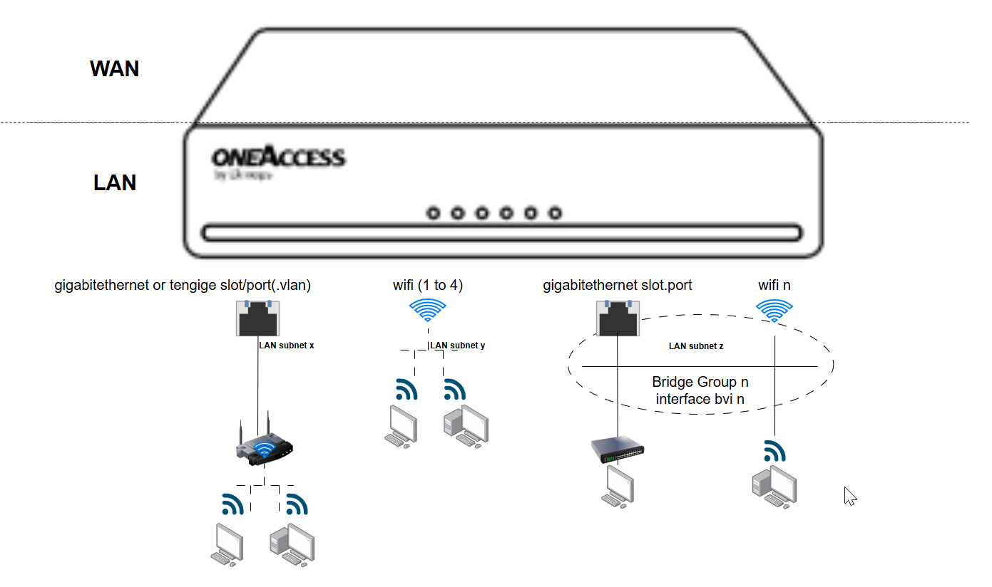
In the most common deployment model, each Wi-Fi interface is associated with its own LAN subnet and hosts the IP address used as the default gateway for wireless devices. In this configuration, wireless and Ethernet networks operate as separate LAN segments and communicate through IP routing.
In some deployments, wireless and Ethernet devices must belong to the same LAN subnet. To support this requirement, Wi-Fi and Ethernet interfaces can be added to the same bridge group.
In this configuration, Ethernet frames are bridged between wired and wireless interfaces, allowing devices to communicate at Layer 2 as if they were connected to the same switch. A Bridge Virtual Interface (BVI) is used to host the IP address associated with the shared LAN subnet.
The following design illustrates common Wi-Fi deployment topologies.
 |
Wi-Fi Connectivity on Routers Without Integrated Wireless LAN
For SD-WAN routers that do not include a Wireless LAN controller, Wi-Fi connectivity can still be provided using one or more external wireless access points.
In this deployment model, the access point is connected to an Ethernet LAN interface, either directly or through an Ethernet switch. The Wi-Fi network is then integrated into the LAN through the Ethernet infrastructure. The corresponding topology is an Ethernet LAN deployment extended with external wireless access points.